My Maslow CNC was suffering from a jumping chain, which is quite alarming when you are standing near the machine. It mucks up the calibration as well, so it is not a desirable thing to have happen. When this happened before, I used some plywood to lift the chain so that it fed onto the sprocket at the correct angle. This never worked too well as the plywood was not quite the correct thickness to guide the chain properly. After another jump of the chain I decided to 3D print some chain guides.
The guides were created in OpenSCAD, which I use exclusively for all my 3D printed objects. It is parametric, so I can type in the height I want the chain slot to be from the base of the guide and the object generated will be of that size. I need two different distances on each side of the machine, so I'll print two slightly different guides.
I had to file out the guide slot a bit in order to get the chain through the hole, but I'll print the second guide a bit bigger. It's working fine so far, we'll have to see if it has solved the jumping problem...
Wednesday, 17 January 2018
XY Table Update
The XY table project has moved on a bit. I've finally printed a couple of single axis mounts for the DVD drive stepper motors. The motors have ended up as the only part of the DVD mechanism to be used in the table. I'm planning on mounting one of the tables on top of another to give me the XY motion I need for the automating of the die shots.
Olympus BHM Panasonic GF1 Micro Four Thirds Camera Mount
Now I have a new LED lighting arrangement on the Olympus microscope I need a way to attach my Panasonic GF1 camera properly. Up until now I've used a tripod to point the camera down the camera port or just rested the camera on top. I have also pointed the camera down an eyepiece, but I end up with vignetting if I do that with a lens. I bought an eyepiece adapter which mechanically is fine, but I ended up with weird rings when I tried to take a photo. I've no idea what was going on. So I 3D printed a camera tube:
there's a taper at the camera port end and I've put some insulation tape in there to get a nice soft tight fit. The top of the tube slides in to a micro four thirds to OM adapter I bought. There's a screw I can use to attach it but the tube is such a good fit it's not necessary. It turns out that even with the thickness of the tube it is still not opaque to light, so I covered the tube in aluminium foil.
I've done a short video showing the tube here:
Tuesday, 9 January 2018
Sinclair Memory Calculator Tear-down
I've bought a Sinclair memory calculator. It's in a bit of a state, but that's good, as I bought it to tear it down. The videos are here:
Part 1:
Part 2:
Friday, 5 January 2018
Radioactive Junk
I buy the odd piece of interesting junk now and again, and I've been a bit wary of some of them maybe being around radioactive materials. So, I have finally got hold of a Geiger counter. Well, bought a kit and assembled it.
I got a GK-B5, which for now lives in a temporary case, namely the cardboard box that it came in:
The Geiger Muller tube is an SBM20 and has about 500V across it, but it's not dangerous as the supply has a very high output impedance. The kit works well, and registers a count of about 25 per minute for background radiation.
Have I found anything radioactive? Well, yes, but I was deliberately looking for something so I scanned a couple of local junk shops. I found four pieces of uranium glassware. It's a pale green glass, the pieces I found were in the form of a jug, two bottles and a tray. So did I find any of the junk I had bought to be radioactive? Well, no, none of the bits I had concerns were radioactive. But, I did find that one of the objectives I had bought for my microscope had a count that was similar to the uranium glass I found. I suspect that it may have been used to look at uranium ore and a piece has lodged in the objective. It's not too concerning but at least the Geiger counter has served it's purpose.
Olympus BHM Microscope LED Light
The BHM microscope that I bought recently was fitted with a light source that was an incandescent bulb. It is driven by a variable transformer PSU. The PSU is quite nice, the bulb not so much. I have a suspicion that the bulb is a replacement that isn't quite the right voltage as it has never been more bright than a bit dim. I decided to build an LED replacement, so ordered some Cree LEDs and set about making a mount for them.
I had a cylinder I had cast from some melted down scrap, and turned it to the diameter of the lamp holder that fits on the back of the microscope.
After it was the correct diameter I drilled some holes that will hold the LED into place:
The LED is then fixed in place with three screws:
The cylinder acts as a heat sink. I had bread-boarded the circuit and checked how hot the circuit and LED got and it doesn't get very hot at all. It's a 1W LED so there's not a lot of scope for dissipation. The connections for the LED run in a milled channel down the cylinder. I put a block of aluminium on the end as a mounting plate for the circuitry and as extra heat-sinking outside of the light holder.
The PSU outputs a.c. which is fine for the bulb but not so good for the LED. I added a bridge rectifier, some dropper resistors and a capacitor to convert the a.c. to a d.c. supply. This mounts on the block on the end of the assembly. Initially I used bits of wire to connect the circuitry to the PSU:
3D printed stand-offs hold the circuit board away from the aluminium block:
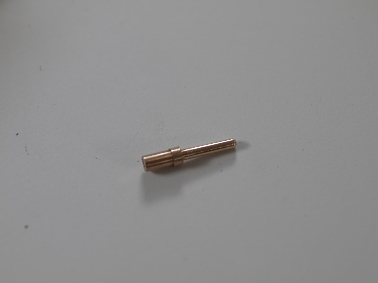
I wasn't very happy with using bits of wire to connect the PSU and didn't fancy hunting around for a suitable connector, so I made one. I turned a couple of pins from phospher bronze:
And 3d printed a shell in two parts. The pins have a shoulder that holds them in to the shell. The pins turned out nicely:
Here's the light in place and generating photons. The LED is positioned very close to the position the bulb filament would have been in and I end up with a pretty even illumination across the field of view.
The light and the connector look like this when assembled:
I may add bolts to hold the connector together, but the pins are a tight fit so I may not. Here's the original bulb in it's holder as a comparison:
The LED leads are soldered across a capacitor for now, I'll tidy them up later. Once I've run this for a while I'll make a PCB to mount the components anyway, so this is probably temporary.
I've got a descriptive video of this LED illumination here: