Search This Blog

Showing posts with label electronics. Show all posts

Thursday, 24 December 2020

Casio CQ-1 Recreation Information

Until I tidy up the github repository, here's some snippets relating to the Casio CQ-1 recreation.

 The first PCB is really a prototype as well, it just fits in the case better than the first prototype. 

Friday, 30 October 2020

Is This the Past, or the Future?

We have a rainwater harvesting system, which comprises a large tank in the garden fed by rainwater, a submerged pump in the tank and a pump controller in a cupboard in the kitchen. Yesterday our washing machine that is fed from the rainwater had it's red 'Check input' light on. Not good. What was even less good was the water that had been squirted up onto the roof of the cupboard. The problem was a diaphragm that is used, I believe, in a pressure switch that the controller uses to determine that it has pumped enough and should switch the pump off. It had split, allowing water into the expansion chamber above it and out of an air bleed hole. 


You can just see the split on the front left of the diaphragm. Well, the obvious thing to do is to get a replacement part. A lot of the time this is not possible, because they are unobtainable or the unit is obsolete and parts are not available any more. Well, I was quite surprised when I found out that this part is indeed available (and in stock). That's mildly unusual, but what makes it more unusual is that my controller is now superseded by another unit. That unit uses an identical diaphragm. The new controller also uses a new lower power controller, but it has been designed with the same footprint and mounting as the old one, so it can be used in the old controller housing. I've not seen this level of parts interchangeability much, maybe not at all.  It means that the design of the new controller has seemingly foregone extra profit from people having to replace controller units in favour of allowing repair and replacement of parts.

This isn't the first problem I've had, a while back a capacitor failed, and I replaced it:

 https://trochilidae.blogspot.com/2018/02/rainwater-harvesting-pump-controller.html


Another surprise that happened during that repair was that the controller was built from standard ICs and components. It is not a microcontroller based design. There is no firmware. If the controller PCB fails it is possible to repair it or even make a new PCB. This controller appears to be repairable for quite some time to come. 

So is this a design from the past, where almost everything was repairable and electrical and electronic equipment even came with circuit diagrams? Or is it a design from the future that uses the minimum disposable parts and doesn't have built-in obsolescence?

Either way, I like it.

Saturday, 12 September 2020

Casio CQ-1

 Casio CQ-1

A long time ago, I had a Casio CQ-1. 


It was a weird machine, I suppose, but it was a clock, and a stopwatch, and a calculator, which makes it pretty useful. And the calculator could tell you what day of the week any date was (well, in it's date range). It could calculate the number of days between two dates. And it was an alarm clock.

Not so long ago the batteries leaked and the CQ-1 was binned. This was a shame and I decided to get hold of another one, so bought one on ebay. This didn't turn out too well, as the device would only start up if I held my finger on one of the clock oscillator pins. I tried simulating a finger with various components, but the little chip seemed only happy with my finger. I never found out why, so I bought another CQ-1, hoping to either get enough bits to fix my original CQ-1 or get a unit I could fix. That didn't work out too well either, as it was utterly dead, and no amount of fingering could get it going again.  Aargh!. Third unit and this time all was well. It calculated dates and the stopwatch worked.

At least all was well until I came to use it after a day or two and the AA battery was flat. Aaargh! again. This CQ-1 has a strange fault where the supply that powers the VFD display seems to power up repeatedly even when the unit is off, and that eventually flattens the battery.

So, I decided to have a go at designing a replacement for the CQ-1 main PCB. This is the one that has the circuitry on it. This is a partially stripped PCB:
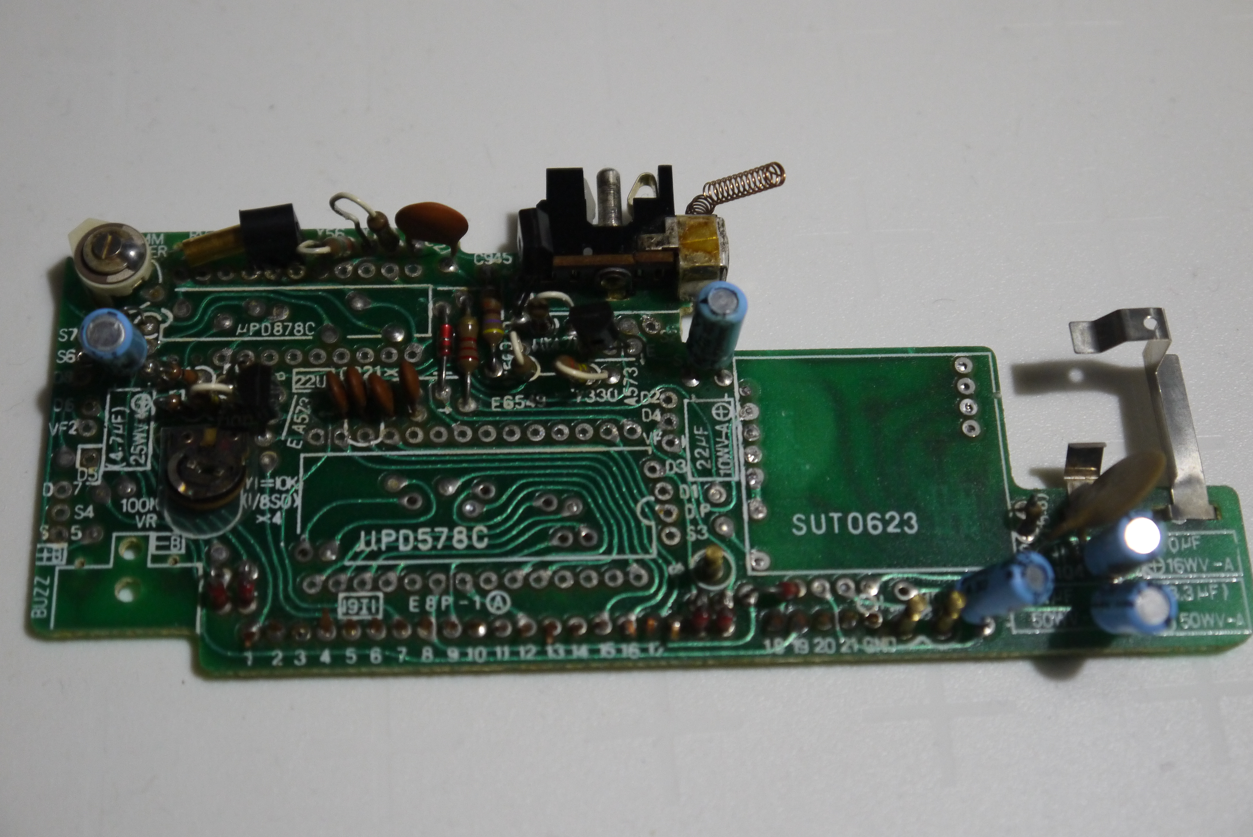
It attaches to a keyboard PCB which has one of the AA battery connections on it. The wire tabs connect to two 1.5V watch batteries that power the clock circuit. 

The first attempt at recreation is this:


There's a prototyping PCB (one of Mike Harrison's prototyping boards) with all the circuitry to create the voltages to run the ARM processor (3V3)and the higher voltage needed to run the VFD segments and digits (about 23V). The filament drive is conveniently 3V3 (ac). The PCB is attached to the front half of a CQ-1 which provides the switches and keys. All this circuitry runs off a single AA battery, or USB. As batteries are an evil that has to be tolerated, I did consider running this off just USB, but decided that it was too limiting. i didn't want to use the original CQ-1 PSU as I've never seen one, and USB is just so convenient. I haven't carried over the silver oxide batteries that run the clock, instead the RTC chip runs directly off the battery. It is a low power chip so that's not a problem. If there's 3V3 then it runs off that too, so you can plug a USB cable in when changing the AA battery.

This is a close up of the prototype PCB.


There's a blue pill providing an ARM processor, programmed with an ST-LINK. There's two dc-dc converters, one to go from 1V5 to 3V3 and one to go from 3V3 to 23V (-ish). The 23V supply is switchable from the processor and turns the display on and off. The VFD is driven from a MAX6921 chip which has a serial connection to the processor. The timekeeping is provided by an MCP7940 chip with it's own crystal. This is attached over I2C to the processor. i took a VFD tube from a donor CQ-1 and that is used as the display. The beeper is also from a CQ-1. Due to the STM32F103C8 on the blue pill not having enough GPIOs to handle all this hardware and scan the keypad, a GPIO expander is used on this PCB to provide more GPIOs. This is accessed using I2C.

Of course, this doesn't fit in the original case, so a V2.0 PCB has been created that does:

This is basically the same circuit, but the dc-dc converters are now in component form on the PCB, and the GPIO expander has been dropped as a larger STM32 chip with more GPIOs has been used. This is capable of all the IO and keypad scanning. It also has more flash and RAM (512K of flash and 64K of RAM). As the STM32F103 chips are all very compatible there are a few options for flash and RAM simply by fitting a different variant of the chip.

I've also added the connections for an OLED display on this PCB so if the CQ-1 VFD is broken then you can use a dot matrix OLED display. The 23V dc-dc converter can be left out if the OLED is used, as well.

Here's the first populated PCB in a case:

It fits nicely, the wires coming out are the ST-LINK programmer wires. The USB power goes in through the battery cover latch hole which I filed out so the USB socket was accessible. The circuit should run off a single AA battery as well (the prototype did, but I've not tested the new PCB yet). I'll need to print a connector for the positive terminal of the battery, the negative is a spring on the keypad PCB.

Here's the front side of the PCB:


Again the beeper and VFD tube are from a CQ-1. The keypad PCB is mounted using 0.1" plug and socket connectors, the spacing was perfect, even though the original CQ-1 uses copper strips held together with plastic.

The PCB needs a modification as I got one signal wrong, the keypad connector is out by 0.1" for five connections, the 23V dc-dc converter inductor whistles, and the mounting hole for the beeper is too small, but other than that I'm very happy with it. It fits the case well.

There's a few things left to do. The display is a bit dim, which is probably the 23V dc-dc converter needing to be 26V or so. There's a lot of code to write if this is going to be the same as a CQ-1 but there's a rudimentary stopwatch and integer-only calculator, together with a clock you can't set, but writing the code is the fun bit...

See it working here:


Some pictures of it operating:


The USB cable that is powering it and the programming wires that come off a header on the PCB:


And displaying some characters that the original just can't manage:


Friday, 8 December 2017

Miele Induction Hob Problem

Miele Induction Hob Problem

We've had a Miele KM5731 for nine years or so, it took a while for me to fit it after we bought it, so it's probably been installed for more like 8 years. Anyway, a few days ago it started to give an error code of FE32.This is the hob, it has four induction coils and some touch buttons:


The error code appears in the power level displays:


Once the error code appears the hob is unusable. The instruction manual isn't much help, it says turn it off and on again. Well, that might work, but it's got progressively harder to conjure away over the past few days. A search on the internet resulted in many useless sites and one very useful Dutch site. From that site it transpires that there are a couple of capacitors on the power PCB that can pop and lead to this error code. I took the hob apart and had a look and indeed there were two capacitors with bulging tops.

They are both 470uF 25V electrolytics, this one has split and opened:


This one has just expanded on top:


I ordered some new high quality capacitors to replace these two and also some to replace the other electrolytics on the PCB. These arrived today and I have replaced the capacitors. So far no sign of FE32, but we'll have to see over the long term whether it's fixed or not.

Interestingly the decent quality (Panasonic) capacitors I ordered were identical to the ones fitted, except for the date code, apart from the two that had popped. So it looks like maybe there was a supplier issue with those two.

UPDATE 13th February 2018
So far there's been no re-occurrence of the problem, so it looks like the capacitors were the problem.

UPDATE 25th March 2021

I have made a video of the disassembly of my hob, it's here:

https://youtu.be/MCJaZrRvgdE


Sunday, 28 May 2017

Video of DRO Operating

Video of DRO Operating

I've made a little video of the DRO operating so you can see how fast the update rate is. It's several readings a second and easily fast enough for anything I do. The gauge data stream is pretty fast and all six channels are read by the main processor over I2C, only three are displayed.


The main TFT is quite slow with big updates, but just about responsive enough when I use the menus.


One thing I was worried about was the auto power-off that the gauges have. After a period of inactivity they shut down, but fortunately all they do is turn the display off. The data stream continues, which is perfect for a DRO like this. It also might explain why the batteries go flat so quickly...

Saturday, 10 December 2016

Equipment Rack

Equipment Rack

I now have quite a few instruments for electronics, some scopes a logic analyser and a thurlby multimeter/serial analyser/scope. the end of the workbench now has a gap after the shelves were built, and I was going to fill it in with a piece of worktop. Then I measured the instruments and found that they all fit in the gap. So, after a quick bit of wood bashing:


I have used some scrap wood and old flooring and made a simple rack for the equipment:


The rack is on wheels so can be moved about. I am hoping that the space freed up on the workbench will be more than I would have gained by filling the gap where the rack sits with more worktop. I think it will as I can have the logic analyser and scope next to something I'm working on and take up no bench space. We'll see.

As it's made of scrap wood, I could just dismantle it if it doesn't work out.


Friday, 2 December 2016

LA4800 Pod

One circuit of a pod and some routing and we have a pod for the LA4800:


It's a bit big as I just wanted to see if the circuit was correct and I anticipated lots of scoping. As it turned out the only problem was the transistor pinouts and the orientation of the pod cable sockets. Neither of which is much of a problem. as the pod works.

Here's a quick trace of some signals on the Epson HX-20 IO port.


The analyser works perfectly as far as I can see, apart from the display problems, which really are a shame.
I had to solder wires on for this test as the clips I ordered haven't arrived yet, but that's fine.

Wednesday, 30 November 2016

Epson HX20 Interface

One of the nice things about older hardware is that a lot of it comes with expansion connectors or other ports that allow you to attach arbitrary hardware to it. The HX-20 is no exception and comes with an expansion port which allows access to the bus signals of the main processor (yes it has two - almost dual core). I wanted a simple IO port so breadboarded a simple 8 bit output latch and 8 bit input circuit using old fashioned 74 series logic.

As a more permanent solution I routed a PCB.


I then used an old PC HDD cable to attach to the HX20 which helpfully uses a standard 0.1" pitch IDC connector. Unhelpfully they have used a different numbering scheme to the rest of the world which means the pin numbers are all jumbled, but that's not and unsolvable problem, just an irritation.

The output port can be used to drive other hardware, I'm going to use this one to drive a relay module:


The bottom two bits of the data bus are wired up on this PCB, so you write to address &H5000 and D0 and D1 will end up latched in the output port. To read inputs you read the same memory location, again D0 and D1 are the data bits that are wired up.

Friday, 8 July 2016

First DRO PCBs

 I've routed the first DRO PCBs. This is the main display PCB with one gauge interface daughter board:


There's the three LED axis displays and the OLED axis label displays. The larger display at the bottom is the TFT that I want to use for diagrams etc.

This is the gauge interface board:


it plugs in like this:


The partially populated display PCB from the rear:


Unfortunately I have a short between the supply rails on the display board, so I'm going to remove the excess copper to try to isolate it.

Wednesday, 16 March 2016

More PCB Milling

I'm experimenting with milling more detailed and double sided PCBs. So far I have tried a smaller cutter (D bit) that was 0.1mm, but I suspect turned out to be a bit larger than that. The fine tracks have disappeared in a few places so it's not usable, but overall it's encouraging.


The four large holes are my attempt at registration pin holes, which failed as the PCB software auto centres the artwork so when I milled the traces they weren't registered with the pin holes properly. I need to experiment with methods of creating these holes.

The second attempt at the double sided OLED watch PCB was more successful. I mistakenly drilled the via holes from the wrong side, I hadn't remembered that the holes are drilled from the bottom of the board, so I milled the top side tracks then drilled holes. Of course they were wrong and this PCB has an extra set of via holes. It is probably just about usable, but I am going to make a new board more suited to milling and also add some of the circuit changes as well.


This second PCB looks a lot better. I cleaned the copper up using some fine wet and dry paper as there's a lot of rough burrs as it comes off the milling machine.
The blue PCB is the one I had made in China, for comparison.

The registration using pins worked well, the program I wrote to generate the pin holes now uses the board outline, which has to be the correct size.


Thursday, 7 January 2016

More Watch

The display is now working, I have functions that display integers and strings and an X-Y positioning function. The display shows text:


The capacitive touch sensors are working too, That's what the OFF OFF means, two sensors are currently off (because I have no finger near the wires). This video shows the capacitive sense inputs in action. You can see OFF swap to ON when I get near the sense wires.


Unfortunately I think the processing of the sense inputs may take up too much current and shorten battery life. I may have to go for the less cool mechanical switches.