

Microtan Arduino Card Part 1
The rack mounted Microtan system has the useful feature that it is, well, rack mounted. This means you can attach anything to it by building a card. After building the cassette interface PCB that uses a serial data connection to save and load data, I was wondering if there was a better way to load and save programs from the Microtan. One that was faster and could maybe read and write directly from and to the SD card without using an intermediate RAM buffer. I could use RS232 and handshaking (might try that sometime), but it's still serial. then I wondered about DMA on the bus. Could I build a card that read and wrote directly to and from memory? The TANBUS does have signals that allow DMA access, so it should be possible. There's a block of memory on the Microtan 65 that isn't accessible, but everything else is. What would do the accesses? Well, why not an Arduino Mega? It runs off 5V and has plenty of GPIOs. With DMA it doesn't have to buffer much data as it can do direct reads and writes to the card. It could also maybe monitor the bus and do bus capture traces. It's not got a very fast processor at 18MHz, but the Tanbus is only 750kHz, so it might be possible to capture traces in code.
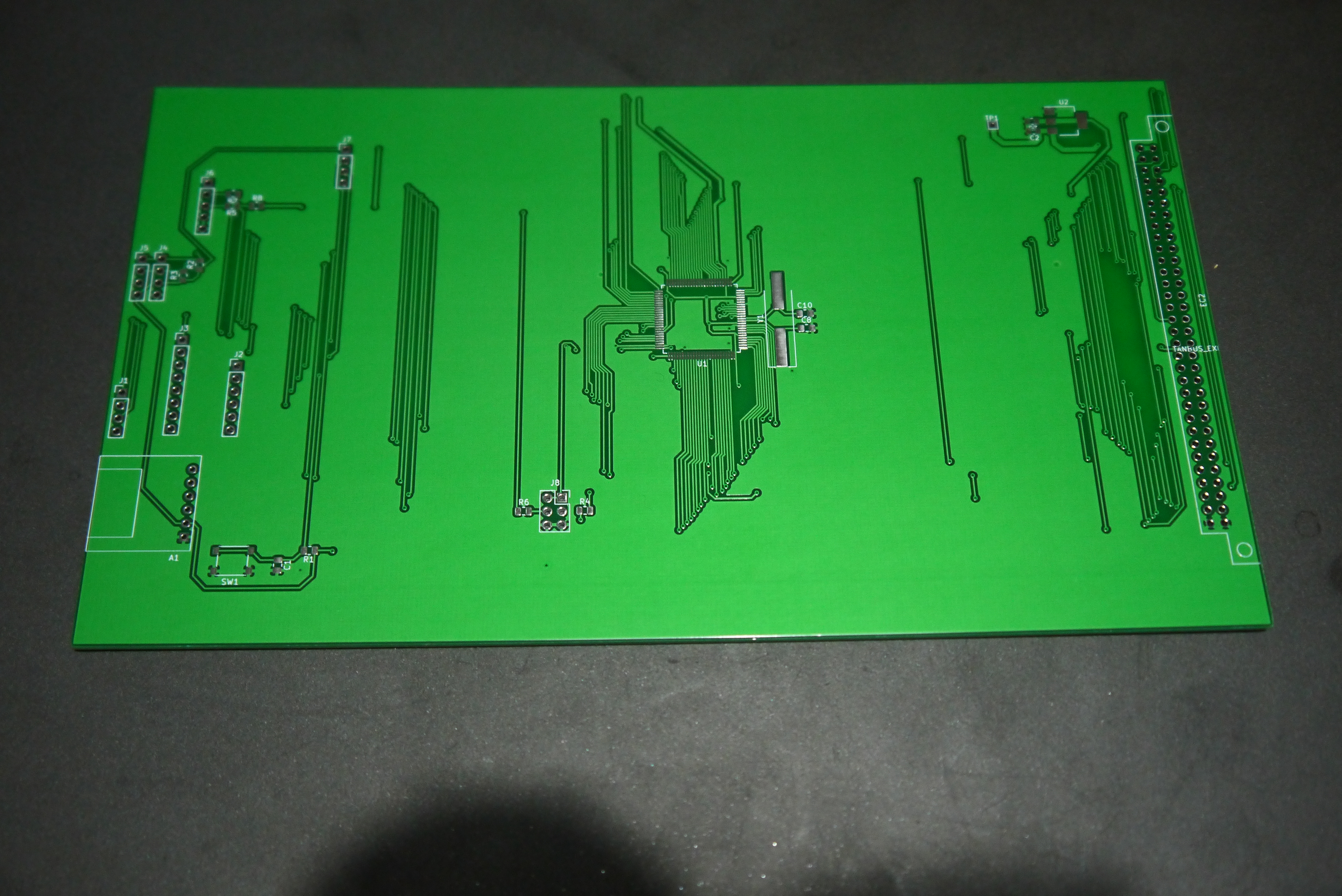
It was worth an experiment, so I made some PCBs that had a Mega Pro embedded on a card that fitted in the rack.

Once populated I ran some simple code to sample the bus asynchronously. This appeared:
Microtan 65 DMA Gadget
00: FE03-FF FE04-7F FE01-0C FE05-FF FE07-FF FE03-FF 0004-FE FE05-0C
08: FE06-FF FE07-FF FE03-FF 0001-FF FE05-FF FE06-FF FE07-FF FE04-FF
10: 0001-71 FE05-FF FE06-FF FE03-FF FE04-FF FE01-7F FE05-FF FE07-FF
18: FE03-FF 0004-FF FE05-DF FE06-FF FE07-FF FE03-FF 0001-6E FE05-FF
20: FE06-FF FE07-FF FE04-FF 0001-00 FE05-FF FE06-FF FE03-FF FE04-7F
28: FE01-04 FE06-FF FE07-FF FE03-FF 0004-FE FE05-00 FE06-FE FE07-FF
30: FE03-FF 0001-FF FE05-FF FE06-FF FE07-FF FE04-FF 0001-01 FE05-FF
38: FE06-FF FE03-FF FE04-FF FE01-FF FE06-FF FE07-FF FE03-FF 0004-FF
40: FE05-9F FE06-FF FE07-FF FE03-FF 0001-FE FE05-FF FE06-FF FE07-FF
48: FE04-FF 0001-04 FE05-FF FE07-FF FE03-FF 0204-FE FE01-04 FE06-FF
50: FE07-FF FE03-FF 0004-FE FE05-00 FE06-FF FE07-FF FE03-FF 0001-FE
58: FE05-FF FE06-FF FE03-FF FE04-FF 0001-09 FE05-FF FE07-FF FE03-FF
60: 0004-FF FE01-DF FE06-FF FE07-FF FE03-FF 0004-6F FE05-87 FE06-FF
68: FE07-FF FE03-FF 0001-FF FE05-FF FE06-FF FE03-FF FE04-FF 0001-00
70: FE05-FF FE07-FF FE03-FF 0004-7E FE01-00 FE06-FF FE07-FF FE03-FF
78: 0004-FF FE05-01 FE06-FF FE07-FF FE04-FF 0001-00 FE05-FF FE06-FF
80: FE03-FF FE04-FF FE01-09 FE05-FF FE07-FF FE03-FF 0004-FF FE01-FF
88: FE06-FF FE07-FF FE03-FF 0004-FF FE05-0F FE06-FF FE07-FF FE04-FF
90: 0001-71 FE05-FF FE06-FF FE03-FF FE04-FE FE01-04 FE05-FF FE07-FF
98: FE03-FF 0004-7E FE01-00 FE06-FF FE07-FF FE03-FF 0001-FE FE05-FF
A0: FE06-FF FE07-FF FE04-FF 0001-C9 FE05-FF FE06-FF FE03-FF FE04-FF
A8: FE01-09 FE05-FF FE07-FF FE03-FF 0004-6F FE01-FF FE06-FF FE07-FF
B0: FE03-FF 0001-FF FE05-FF FE06-FF FE07-FF FE04-FF 0001-00 FE05-FF
B8: FE06-FF FE03-FF FE04-FE FE01-00 FE05-FF FE07-FF FE03-FF 0004-FF
C0: FE05-01 FE06-FF FE07-FF FE03-FF 0001-FF FE05-FF FE06-FF FE07-FF
C8: FE04-FF 0001-51 FE05-FF FE06-FF FE03-FF FE04-FF FE01-81 FE04-FF
D0: FE07-FF FE03-FF 0004-FF FE05-15 FE06-FF FE07-FF FE03-FF 0001-FF
D8: FE05-FF FE06-FF FE07-FF FE04-FF 0001-00 FE05-FF FE06-FF FE03-FF
E0: FE04-FE FE01-00 FE06-FF FE07-FF FE03-FF 0004-FF FE05-80 FE06-FF
E8: FE07-FF FE03-FF 0001-FF FE05-FF FE06-FF FE07-FF FE04-FF 0001-19
F0: FE05-FF FE07-FF FE03-FD FE04-FF FE01-05 FE06-FF FE07-FF FE03-FF
F8: 0004-FF FE05-9F FE06-FF FE07-FF FE03-FF 0001-FF FE05-FF FE06-FF
The 16 bit numbers are the address bus, and the addresses shown correspond to the POLLKB loop in the TANBUG program. So it seems to work for the addresses. The data bus isn't as good, but that could be because the trace is asynchronous and the data bus doesn't have data on it as long as the address bus does.
I then wrote some code that used the DMA mechanism to read data from memory areas. This stops the processor from accessing the bus and takes over as a bus master. Data can then be read and written as desired.
The principle looks good, but this card has a few problems:
1. It isn't fast enough to capture bus traffic reliably.
2. There's not a lot of RAM on a Mega, so dumping large amounts of the memory space of the Microtan is a problem.
3. I didn't include an SD card, which is a very useful way of getting data into and out of the card and the Microtan
To attempt to overcome these problems a V2.0 card was laid out.
This one uses an STM32F103 with 1Mb of flash and 96Kb of RAM. This is a much more usable size of memory, the RAM allows all of the Microtan memory to be dumped with space to spare, and the large amount of flash allows images to be stored. The processor is much faster too, running at 72MHz.
The device supply is up to 3V6 so a 3V3 regulator is used and the GPIOs that deal with the bus signals are 5V tolerant. The 5V tolerance is only functional when the GPIOs are set up as inputs, but that is a the normal state while monitoring the bus. When the bus is driven and GPIOs are outputs, however then there could be a problem if the circuitry on the Microtan has a pull-up, for instance. We'll have to see how delicate the STM32F103 chip is when faced with this sort of work.
I've only tried this V2.0 card out briefly and the signs aren't good. I don't think that the ARM processor has been destroyed, but the card doesn't seem to work. I get addresses of 0,1,2,3,0,1,2,3,0,... and the data bus is always 0xFF. It's all a bit too deterministic to be voltage thresholds, well, I think so at the moment. I'll have to investigate...


No comments:
Post a Comment