

Casio CQ-1
A long time ago, I had a Casio CQ-1.

At least all was well until I came to use it after a day or two and the AA battery was flat. Aaargh! again. This CQ-1 has a strange fault where the supply that powers the VFD display seems to power up repeatedly even when the unit is off, and that eventually flattens the battery.
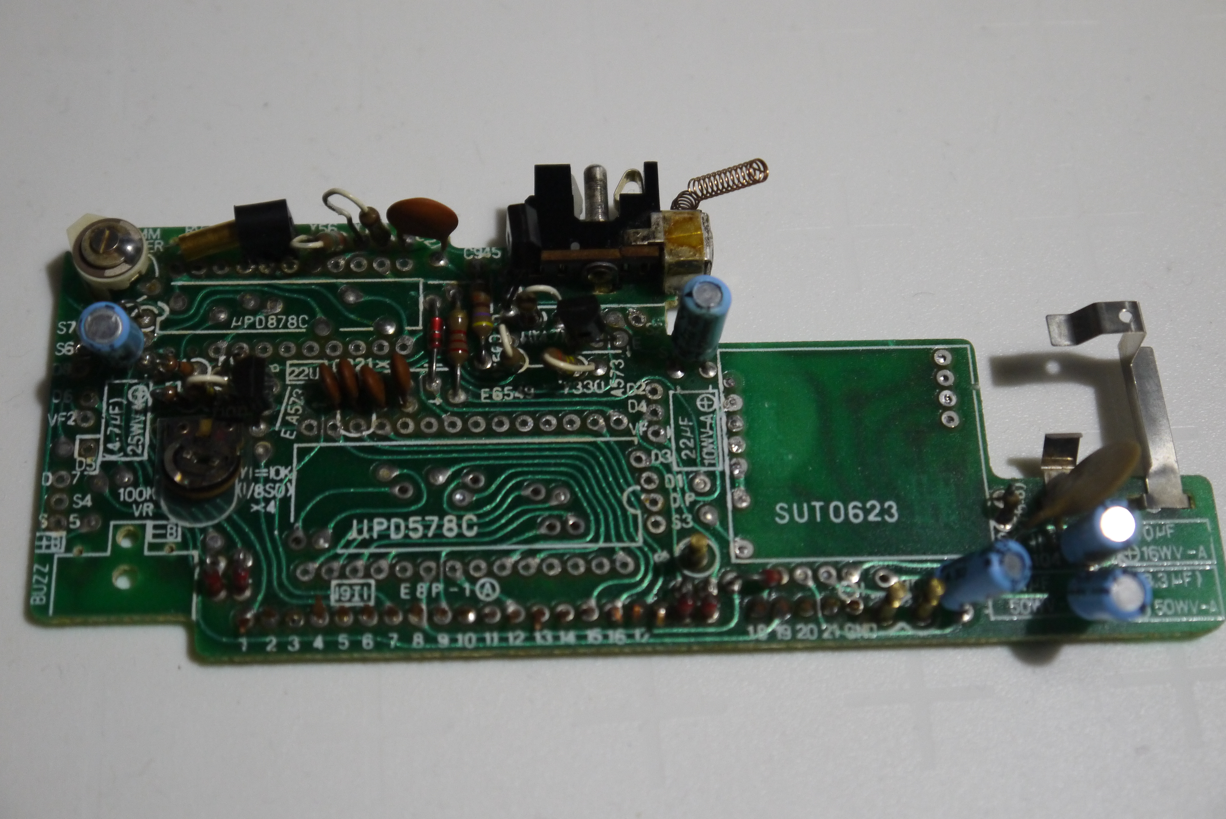
So, I decided to have a go at designing a replacement for the CQ-1 main PCB. This is the one that has the circuitry on it. This is a partially stripped PCB:
It attaches to a keyboard PCB which has one of the AA battery connections on it. The wire tabs connect to two 1.5V watch batteries that power the clock circuit.
The first attempt at recreation is this:


There's a blue pill providing an ARM processor, programmed with an ST-LINK. There's two dc-dc converters, one to go from 1V5 to 3V3 and one to go from 3V3 to 23V (-ish). The 23V supply is switchable from the processor and turns the display on and off. The VFD is driven from a MAX6921 chip which has a serial connection to the processor. The timekeeping is provided by an MCP7940 chip with it's own crystal. This is attached over I2C to the processor. i took a VFD tube from a donor CQ-1 and that is used as the display. The beeper is also from a CQ-1. Due to the STM32F103C8 on the blue pill not having enough GPIOs to handle all this hardware and scan the keypad, a GPIO expander is used on this PCB to provide more GPIOs. This is accessed using I2C.
Of course, this doesn't fit in the original case, so a V2.0 PCB has been created that does:

This is basically the same circuit, but the dc-dc converters are now in component form on the PCB, and the GPIO expander has been dropped as a larger STM32 chip with more GPIOs has been used. This is capable of all the IO and keypad scanning. It also has more flash and RAM (512K of flash and 64K of RAM). As the STM32F103 chips are all very compatible there are a few options for flash and RAM simply by fitting a different variant of the chip.
I've also added the connections for an OLED display on this PCB so if the CQ-1 VFD is broken then you can use a dot matrix OLED display. The 23V dc-dc converter can be left out if the OLED is used, as well.
Here's the first populated PCB in a case:

It fits nicely, the wires coming out are the ST-LINK programmer wires. The USB power goes in through the battery cover latch hole which I filed out so the USB socket was accessible. The circuit should run off a single AA battery as well (the prototype did, but I've not tested the new PCB yet). I'll need to print a connector for the positive terminal of the battery, the negative is a spring on the keypad PCB.
Here's the front side of the PCB:

Again the beeper and VFD tube are from a CQ-1. The keypad PCB is mounted using 0.1" plug and socket connectors, the spacing was perfect, even though the original CQ-1 uses copper strips held together with plastic.
The PCB needs a modification as I got one signal wrong, the keypad connector is out by 0.1" for five connections, the 23V dc-dc converter inductor whistles, and the mounting hole for the beeper is too small, but other than that I'm very happy with it. It fits the case well.
There's a few things left to do. The display is a bit dim, which is probably the 23V dc-dc converter needing to be 26V or so. There's a lot of code to write if this is going to be the same as a CQ-1 but there's a rudimentary stopwatch and integer-only calculator, together with a clock you can't set, but writing the code is the fun bit...


And displaying some characters that the original just can't manage:


