It was the time for the first hair cut for the little one, and being a squirrel type person that doesn't throw much away until it has been used a couple of times, it seemed a bit wasteful to just throw the hair cutting away. After all, we won't have hair from the first hair cut again.
Then I came across this page:
https://allabout-japan.com/en/article/3553/
It seemed a good idea to keep the hair and attempt to make a brush with it sometime. Then I came across this site:
which mentions that human hair brushes is only made from the hair of babies. The hair I had collected is just such hair. "What was the reason for this?" I thought. Off to the microscope to have a look at a hair.
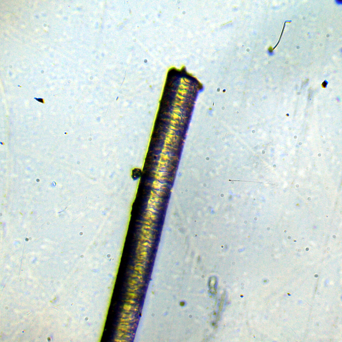
This is the cut end at 10x:
You can see the flat chopped off end, and also some features that look like growth rings. This is a less clear higher (20x) magnification view:
A view at 40x:
The uncut end, which is the first part of the hair that grew looks like this (also at 20x):
This end is much thinner and doesn't have a sharp cutoff. This makes it much finer for brushmaking, I assume, and may be why this is used rather than other, later, cuts.
Wednesday, 28 February 2018
The £500 Dirty Photo
I've been attempting to stitch together sets of photos from die shots for ages. I've managed about three so far, one of which was a big one. The latest attempt has been a failure on every computer I have, and each failure has taken hours in some cases, even overnight. The computers I have are mainly second hand and none of them are very modern or powerful.
Having a definite job to do I decided to buy a more powerful machine to do it on. So I spent £500 or so on a new (ok second hand) machine.
The result is a 386MB TIF file. I can't really post all of it here, so I've got a scaled down version:
This is an 8Mb version of the file. It's about 2000 pixels on a side, which is considerably smaller than the 10000 pixels on a side that the full image uses. The zoom that is possible on the full image is much greater than this scaled down version.
Unfortunately there's some dirt on these photos, which I'm not very worried about as I can retake some or all of the photos and rerun the panorama generation. The dirt is in the middle of the ROM so not the best place it could have ended up.
So there we have it, I spent £500 to get a dirty photograph.
Wednesday, 17 January 2018
Olympus BHM Panasonic GF1 Micro Four Thirds Camera Mount
Now I have a new LED lighting arrangement on the Olympus microscope I need a way to attach my Panasonic GF1 camera properly. Up until now I've used a tripod to point the camera down the camera port or just rested the camera on top. I have also pointed the camera down an eyepiece, but I end up with vignetting if I do that with a lens. I bought an eyepiece adapter which mechanically is fine, but I ended up with weird rings when I tried to take a photo. I've no idea what was going on. So I 3D printed a camera tube:
there's a taper at the camera port end and I've put some insulation tape in there to get a nice soft tight fit. The top of the tube slides in to a micro four thirds to OM adapter I bought. There's a screw I can use to attach it but the tube is such a good fit it's not necessary. It turns out that even with the thickness of the tube it is still not opaque to light, so I covered the tube in aluminium foil.
I've done a short video showing the tube here:
Friday, 5 January 2018
Olympus BHM Microscope LED Light
The BHM microscope that I bought recently was fitted with a light source that was an incandescent bulb. It is driven by a variable transformer PSU. The PSU is quite nice, the bulb not so much. I have a suspicion that the bulb is a replacement that isn't quite the right voltage as it has never been more bright than a bit dim. I decided to build an LED replacement, so ordered some Cree LEDs and set about making a mount for them.
I had a cylinder I had cast from some melted down scrap, and turned it to the diameter of the lamp holder that fits on the back of the microscope.
After it was the correct diameter I drilled some holes that will hold the LED into place:
The LED is then fixed in place with three screws:
The cylinder acts as a heat sink. I had bread-boarded the circuit and checked how hot the circuit and LED got and it doesn't get very hot at all. It's a 1W LED so there's not a lot of scope for dissipation. The connections for the LED run in a milled channel down the cylinder. I put a block of aluminium on the end as a mounting plate for the circuitry and as extra heat-sinking outside of the light holder.
The PSU outputs a.c. which is fine for the bulb but not so good for the LED. I added a bridge rectifier, some dropper resistors and a capacitor to convert the a.c. to a d.c. supply. This mounts on the block on the end of the assembly. Initially I used bits of wire to connect the circuitry to the PSU:
3D printed stand-offs hold the circuit board away from the aluminium block:
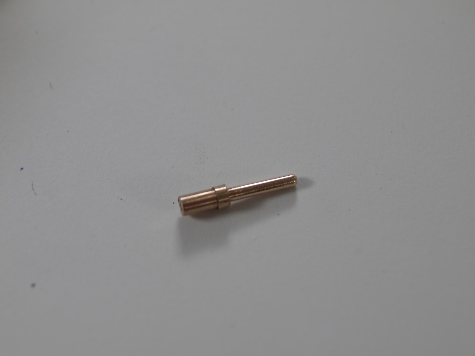
I wasn't very happy with using bits of wire to connect the PSU and didn't fancy hunting around for a suitable connector, so I made one. I turned a couple of pins from phospher bronze:
And 3d printed a shell in two parts. The pins have a shoulder that holds them in to the shell. The pins turned out nicely:
Here's the light in place and generating photons. The LED is positioned very close to the position the bulb filament would have been in and I end up with a pretty even illumination across the field of view.
The light and the connector look like this when assembled:
I may add bolts to hold the connector together, but the pins are a tight fit so I may not. Here's the original bulb in it's holder as a comparison:
The LED leads are soldered across a capacitor for now, I'll tidy them up later. Once I've run this for a while I'll make a PCB to mount the components anyway, so this is probably temporary.
I've got a descriptive video of this LED illumination here:
Tuesday, 26 September 2017
Prototype X-Y Table
The new microscope came with a nice XY stage, but the slide holder was missing. I made one from a cheap XY table. The XY stage is manual, which is fine for adhoc looking at dies, but for photographing dies and then stitching photos there's a lot of photos. It's tedious doing it manually. So I prototyped an XY table from DVD drive stepper motor assemblies.
I had an arduino and two stepper drivers, so connected it all up;
The result is here, the two stepper drivers are being driven with the same signals.
And another view.
I'll have to make a stage block with a dovetail to mount this on the microscope. I may also remove material from the top table as it could do with being a bit lighter.
Wednesday, 9 December 2015
Microscope Reflector
A few months ago I bought a couple of old microscopes from a junk shop. They were pretty cheap, but the carriages were seized. I managed to free them up and they work nicely, but on one of them the mirror used to reflect light onto the sample was missing. It was a simple disc shaped mount, so I turned one up on the lathe:
The metal is shiny enough for this to be good enough to use without a mirror. i may cut a piece of mirror to fit, or, more likely, I will add some form of LED illumination. Messing about with a mirror is a bit of a pain anyway.

 Posts
Posts