Search This Blog

Showing posts with label light. Show all posts

Tuesday, 25 June 2019

Making a Night Light from an IKEA LED Lamp

After a request for some night lights I remembered that I had some IKEA motion sensitive LED lamps that were bought for use in cupboards. One is still in use, the other (they come in packs of 2) was just lying about. They are easy to fix to walls and battery powered, so no trailing cables. I tried one as a night light months ago, but it was very bright and came on during the day as well, so it was removed from duty.

Thinking about the new request, I wondered if the lamp could be modified to add a 'darkness only' feature. Dismantling the lamp revealed a standard PIR chip inside: the BISS0001. Looking at the datasheet revealed even more good news: the chip has a function that  disabled the output from triggering if it detects light. The example circuit has the components for this feature included.

I ordered the parts (100k resistor and an LDR) after working out the values I needed.

I modified one lamp and it didn't work, this was due to the routing of tracks on the PCB, so I lifted the pin on the IC and added the components directly to the pin. SOIC chips don't have robust pins, so bending it up once is about all it can manage. Any more flexing and the pin falls off.

After adding the components correctly, the lamp now only triggers and turns the LEDs on when it is dark. I've also removed three of the four series resistors that current limit the LEDs, as the amount of light given off was too much for a night light.

You also have the option of changing the time that the lamp stays on for, by changing the value of a resistor (or capacitor). This is detailed in the datasheet.

Lift the pin 9 leg:

Then put a 100k resistor from pin 9 to pin 11:


The LDR (light dependent resistor) looks like this:


I used my CNC router to cut a hole that matched the shape of the LDR and glued it in place:


The legs from the LDR wrap around the PCB quite nicely:


One leg can be soldered to the track at the edge of the PCB, the other requires a wire to run to pin 9:


I have modified one of the lamps to have a longer ON time, the rest are as they came. They've been running for a while now and are pretty useful.

These are the LDRs I used:
https://www.ebay.co.uk/itm/192823191519
The resistor was a standard 1206 100k surface mount resistor.


Friday, 5 January 2018

Olympus BHM Microscope LED Light

The BHM microscope that I bought recently was fitted with a light source that was an incandescent bulb. It is driven by a variable transformer PSU. The PSU is quite nice, the bulb not so much. I have a suspicion that the bulb is a replacement that isn't quite the right voltage as it has never been more bright than a bit dim. I decided to build an LED replacement, so ordered some Cree LEDs and set about making a mount for them.

I had a cylinder I had cast from some melted down scrap, and turned it to the diameter of the lamp holder that fits on the back of the microscope.
After it was the correct diameter I drilled some holes that will hold the LED into place:


 The LED is then fixed in place with three screws:


The cylinder acts as a heat sink. I had bread-boarded the circuit and checked how hot the circuit and LED got and it doesn't get very hot at all. It's a 1W LED so there's not a lot of scope for dissipation. The connections for the LED run in a milled channel down the cylinder. I put a block of aluminium on the end as a mounting plate for the circuitry and as extra heat-sinking outside of the light holder.


The PSU outputs a.c. which is fine for the bulb but not so good for the LED. I added a bridge rectifier, some dropper resistors and a capacitor to convert the a.c. to a d.c. supply. This mounts on the block on the end of the assembly. Initially I used bits of wire to connect the circuitry to the PSU:


3D printed stand-offs hold the circuit board away from the aluminium block:


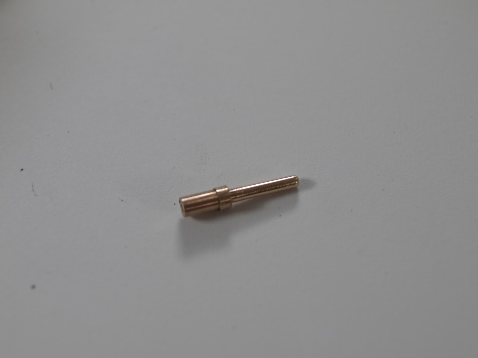
I wasn't very happy with using bits of wire to connect the PSU and didn't fancy hunting around for a suitable connector, so I made one. I turned a couple of pins from phospher bronze:


And 3d printed a shell in two parts. The pins have a shoulder that holds them in to the shell. The pins turned out nicely:


Here's the light in place and generating photons. The LED is positioned very close to the position the bulb filament would have been in and I end up with a pretty even illumination across the field of view.


 The light and the connector look like this when assembled:


I may add bolts to hold the connector together, but the pins are a tight fit so I may not. Here's the original bulb in it's holder as a comparison:


The LED leads are soldered across a capacitor for now, I'll tidy them up later. Once I've run this for a while I'll  make a PCB to mount the components anyway, so this is probably temporary.

I've got a descriptive video of this LED illumination here: