Search This Blog

Showing posts with label pcb. Show all posts

Wednesday, 23 June 2021

 Re-using a Broken Television as a Monitor


or


What To Do With a Broken Television when You Can't Fix It


I was given a broken television.  Technically this television was doubly broken: once when the HDMI inputs stopped working and once when everything stopped working. After the first fault it was taken to a television repair shop (yes, they do still exist) and they couldn't fix it as the parts are not available. I had a look at it on that occasion and found that some RGB inputs did still work, so we fed a signal in there and that allowed the television to live a little longer.

After the second failure nothing appeared on the screen at all, and the backlight did not switch on, so I was given the television to see if I could fix it or do something with it.

The television is an LG 39LE4900 and looks like almost every other television on the planet. Once opened I found a power supply PCB


 and a control PCB:


I also found an inverter PCB, under a metal cover, which powers the backlights:


and what I later found out was a TCON PCB, also under a metal cover:


I had a quick look at the boards and nothing seemed to be obviously wrong. When I powered the television up nothing appeared on the screen and the backlights were off. The remote control worked, in that it turned the television on, but nothing appeared on the screen. I used a torch to see if the LCD was displaying something even though the backlights were off and it wasn't.

I managed to find a service manual on the internet for a similar model, but the control PCB was the only board that the manual had schematics for. I thought this was a bit odd at the time, but it actually makes sense, I'll explain later. unfortunately, as the service manual model wasn't exactly the model I had, all of the component numbers were different to my PCB. I could work out that there was basically one large, presumably custom, chip that controlled almost everything. I checked voltages of power supplies and everything seemed fine.

I also tried to find a serial output from the board that worked, but no luck.

The next step was to get some replacement PCBs from ebay. I did this and eventually replaced all of the PCBs and found that the television still didn't work. This was a bit odd. I then took the step of buying a complete new screen (and a couple more PCBs) to see if that would work with the old and new PCBs. It didn't. This was a bit surprising as I had expected to get something working at this point. 

I then started looking at the PCBs in more detail and found that the TCON board and inverter were made by AUO, and there was actually a datasheet for them. Well, sort of. There was a datasheet for the LCD and backlight and TCON and inverter PCBs, all bundled as a module. AUO seems to sell this as a module that manufacturers can use in their products. LG have done this and then added a PSU and controller PCB. This explains why the controller was the only PCB with schematics in the service manual. The  rest of the electronics was bought in. (Except maybe the PSU which I think is a standard LG board).

The LCD/backlights/TCON/Inverter can be thought of as a larger version of a 16x02 LCD module. That also has a display, backlight, and driver circuit. The only difference is the size of the LCD and the interface used. With the AUO datasheet I now had details of the two connectors that the module provides, one for data and one for backlight. The data input is LVDS.

After another search, I found that the schematic for the PSU PCB was also on the internet, which was useful as I could then hardwire the supply to the LCD backlights. After having done this, I found that the backlights worked fine on both screens. This was good news.

 I then decided that fixing the television wasn't really practical, but I might stand a chance at turning it into a monitor. I'd recently fixed the display on my Novena


 laptop so had played around with LCD panels and knew I could get cheap driver PCBs that would take VGA or HDMI and drive an LVDS interface.

I decided to make a hacked together VGA to LVDS adapter PCB attached to a flat cable connector adapter PCB. The VGA/LVDS adapter needs +5V, whereas the PSU PCB in the television only provided +24V or +12V so I had to also use a DC-DC converter to power it. I hardwired the LVDS signals from the adapter PCB to the flat cable PCB using wires. I cut the connector that the adapter PCB supplied off the end.

Once this monster was all wired up and attached to the television, power was applied and a laptop supplied a VGA signal. And it worked. the picture was upside down, but the laptop could flip that and once done the television now displayed a nice stable picture. Well, it did when I could accurately and firmly attach the flat cable from my PCB to the TCON board. I'd been unable to get the connector that the LG control board used, so I'd bought the one that the TCON board used. This connector rather than being the FPC type connector that attaches to the end of the flat cable, attached to a connector that fits round the end of the cable. 


This meant that I had to use a piece of folded paper to hold the bare flat cable in ot the connector. I also tried 3D printing a flat spacer to wedge in the socket, but it wasn't ideal. In the end I bought a couple of new cables that were the same length as the original but had the connector on both ends rather than just one end. These work perfectly.

 With this mess of wires and boards working I decided to make a PCB. This would mean that the electronics and wiring could be tidied up and I could use one PCB rather than two or three. 


The VGA LVDS adapter was mounted on the new PCB, as was the DC-DC converter. The footprint I used for the converter was a very generic one, which lets me wire almost any DC-D converter I can find on to the board. The wiring holds the converter in place.


I also put a footprint for a Blue Pill on this PCB so I have the option of using that to perform housekeeping functions like turning the supply on and off and providing a timer to turn off the screen after a certain time. I haven't used the Blue pill to do this yet, I just turn the monitor on and off at the mains.

I can also use this PCB as a general Blue pill breakout PCB. I have five PCBs and will probably only ever use two, so the other three can be repurposed.

The PCB fits nicely in on the mounting holes that the AUO module provides, and the VGA connector is accessible once some metalwork has bee cut away.

I've been using the monitor for a few weeks now and it seems ot work fine. I'm making a PCB for the second screen as well, so I'll have that up and running too, I hope. I checked the screen with the first PCB I made and it does also work.

Why the televisions didn't work with the new control PCBs I don't know. I have tested every other PCB I bought and they all work fine. Are the controllers broken? Or do they need some magic setup? I don't know. I'm going to strip them for parts.

Details

The connection between the TCON PCB and the VGA-LVDS adapter:

The 12V supply was used to power the TCON board. The VGA-LVDS PCB needed +5V so the DC-DC converter was used to provide that. I used a variable DC-DC onverter and set it to +5V running from the +12V supply. I measured about 500mA drawn by the adapter so used 1.5A or 2A converters.

The PSU was hardwired to power on. This was done with a wire link on the PSU PCB. Using the schematic I managed to find an appropriate supply and signal to use. (PWR_ON connected to 3V5).

Connections between TCON and LVDS adapter:


VGA-LVDS                TCON

O0+    O0-                CH1_0+    CH1_0-

O1+    O1-                CH1_1+    CH1_1- 

O2+    O2-                CH1_2+    CH1_2-

GND                         GND

OC+    OC-               CH1_CLK+    CH1_CLK-

O3+    O3-                CH1_3+    CH1_3-

E0+    E0-                CH2_0+    CH2_0-

E1+    E1-                CH2_1+    CH2_1- 

E2+    E2-                CH2_2+    CH2_2-

GND                         GND

EC+    EC-               CH2_CLK+    CH2_CLK-

E3+    E3-                CH2_3+    CH2_3-

                                  VDD  +12V

                                LVDS_SEL: Open (HS)

(Closed is JEIDA, which didn't seem correct from the AUO datasheet)


Videos

I have a series of videos that show the work I did.


Thursday, 24 December 2020

Casio CQ-1 Recreation Information

Until I tidy up the github repository, here's some snippets relating to the Casio CQ-1 recreation.

 The first PCB is really a prototype as well, it just fits in the case better than the first prototype. 

Thursday, 26 November 2020

All This to Get Back Where It Started

 All This to Get Back Where It Started

Storing scrap PCBs is all well and good but what do you do with them? After buying a vacuum desoldering machine (wonderful piece of kit), I decided to dismantle the scrap PCBs that I'd been holding on to for years. One of the PCBs I removed components from was a VCR which had a large vacuum fluorescent display on it:


Underneath the display was a controller chip:


It is a Mitsubishi M50957-199SP. I didn't know what that was, but fortunately there is data on the web about it, and it turns out to be a 6502 micro-controller that goes by the family name of MELP. It's a mask-ROM device (the 199SP denotes the actual code loaded into the ROM) and has several peripheral devices embedded in the package as well as the 6502 processor. It's in a slightly odd 64 pin package with a smaller than 0.1 inch pin pitch. It has built in high voltage drivers for the VFD, which would be nice, if it wasn't mask-ROM based. That is a real show stopper if you want to do anything with these chips. Mitsubishi, though, built in a 'microprocessor mode' which can be set up at reset by pulling a pin high. That then causes the address and data busses to be sent out of what would have been IO ports, together with a couple of control lines (RW and SYNC). That allows the device to run off entirely external memory. OK, we can do something with this device now...

I really only wanted to fiddle with the chip, so started thinking along the lines of a 'trainer' or development board, something like the Sinclair MK14 microprofessor or AIM 65. After a few days of musing and then a couple of weeks of PCB layout I came up with this:


Well, yes, there's two of them. The one of the left is the first populated PCB, and it has the VFD and MELP from the VCR. There's a keypad made from MX style keys, they are much nicer to type on than tactile switches. The VFD requires a high voltage to run, so there's a DC-DC converter for that. The VFD filament requires a driver circuit so I included that, but ended up just using 3V3 on this VFD. The high voltage is switched to the VFD using two MAX6921 driver chips. There's an SD card reader for storing programs and an OLED display for extra information when a VFD is fitted and as the only display if a VFD isn't fitted. I only have one of these VFDs, after all. The VFD is mounted on a plug-in adaptor board (perfboard here) so in theory you could attach a completely different VFD if you had one. 

The whole thing is pulled together with an ARM STM32H742, which attaches to the external address and data bus of the MELP and emulates external ROM and RAM (I suppose it actually only emulates RAM, but the MELP doesn't know that). This ARM is a bit of a beast, it runs at 480MHz, has 2MB of flash and 1MB of RAM. It was a bit of a pain to get going as it doesn't have very good (or indeed any) support in the Arduino IDE. I ended up adding my own board definition to the IDE for this PCB. It's odd that there's no generic STM32H7xx board as there is for the STM32Fxxx devices. I suppose they are more common due to the blue pills. This device is also quite pricey, at about £9 each. I noticed the price when I inadvertently ran one chip at 5V for a few days. It turns out that they will run at 5V, but not for long... Then you have to spend an hour or so desoldering a 100pin QFP before fitting a new one.

The VFD has a lot of segments, and so I had to fit two MAX6921s. 

It means there is plenty of scope for displaying useful information about the address and data buses.

So far I've built some code that drives the 6502 through a short program. This program sets some configuration bits and then dumps memory to a fixed address. I wanted to see if I could change the MELP mode to one that would allow access to the mask ROM within the device, but it does look like the internal ROM is not accessible in any mode that 'microprocessor mode' can access.

The code does, however, drive the MELP and supply data from emulated memory when it needs to. You can see the program running in this video:


As I had five PCBs I had a look on eBay for more MELP chips, and did find some. They are slightly different, M50959-133SP, which has more on-board RAM and a different mask ROM. They do work though, so I have enough for the other PCBs.

I can also use this PCB to test VFDs as it has segment/digit drivers and a high voltage adjustable supply and a filament driver. All I need to do is make an adaptor board for each different display type.

As well as a trainer for the 6502/MELP, I'm thinking of adding code that allows this to be an ARM trainer as well. It's probably not going to be as simple to look at ARM peripherals and do a spot of machine code programming as the 6502, but could be fun fiddling with a 480MHz processor at machine code level. The SD card reader means that you don't lose anything you've done, and you can even build large programs on a PC then transfer it over on a card.


Saturday, 12 September 2020

Casio CQ-1

 Casio CQ-1

A long time ago, I had a Casio CQ-1. 


It was a weird machine, I suppose, but it was a clock, and a stopwatch, and a calculator, which makes it pretty useful. And the calculator could tell you what day of the week any date was (well, in it's date range). It could calculate the number of days between two dates. And it was an alarm clock.

Not so long ago the batteries leaked and the CQ-1 was binned. This was a shame and I decided to get hold of another one, so bought one on ebay. This didn't turn out too well, as the device would only start up if I held my finger on one of the clock oscillator pins. I tried simulating a finger with various components, but the little chip seemed only happy with my finger. I never found out why, so I bought another CQ-1, hoping to either get enough bits to fix my original CQ-1 or get a unit I could fix. That didn't work out too well either, as it was utterly dead, and no amount of fingering could get it going again.  Aargh!. Third unit and this time all was well. It calculated dates and the stopwatch worked.

At least all was well until I came to use it after a day or two and the AA battery was flat. Aaargh! again. This CQ-1 has a strange fault where the supply that powers the VFD display seems to power up repeatedly even when the unit is off, and that eventually flattens the battery.

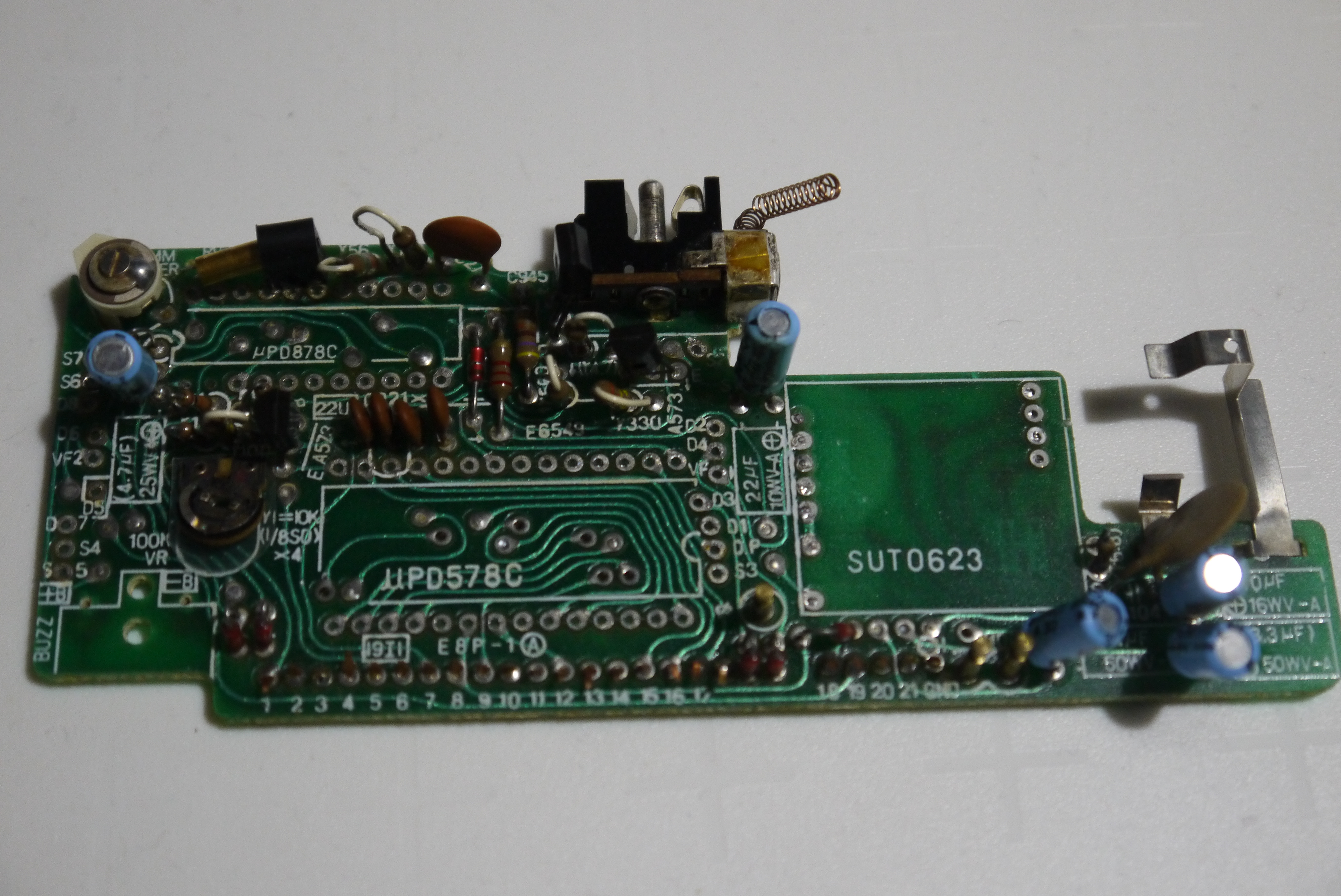
So, I decided to have a go at designing a replacement for the CQ-1 main PCB. This is the one that has the circuitry on it. This is a partially stripped PCB:

It attaches to a keyboard PCB which has one of the AA battery connections on it. The wire tabs connect to two 1.5V watch batteries that power the clock circuit. 

The first attempt at recreation is this:


There's a prototyping PCB (one of Mike Harrison's prototyping boards) with all the circuitry to create the voltages to run the ARM processor (3V3)and the higher voltage needed to run the VFD segments and digits (about 23V). The filament drive is conveniently 3V3 (ac). The PCB is attached to the front half of a CQ-1 which provides the switches and keys. All this circuitry runs off a single AA battery, or USB. As batteries are an evil that has to be tolerated, I did consider running this off just USB, but decided that it was too limiting. i didn't want to use the original CQ-1 PSU as I've never seen one, and USB is just so convenient. I haven't carried over the silver oxide batteries that run the clock, instead the RTC chip runs directly off the battery. It is a low power chip so that's not a problem. If there's 3V3 then it runs off that too, so you can plug a USB cable in when changing the AA battery.

This is a close up of the prototype PCB.


There's a blue pill providing an ARM processor, programmed with an ST-LINK. There's two dc-dc converters, one to go from 1V5 to 3V3 and one to go from 3V3 to 23V (-ish). The 23V supply is switchable from the processor and turns the display on and off. The VFD is driven from a MAX6921 chip which has a serial connection to the processor. The timekeeping is provided by an MCP7940 chip with it's own crystal. This is attached over I2C to the processor. i took a VFD tube from a donor CQ-1 and that is used as the display. The beeper is also from a CQ-1. Due to the STM32F103C8 on the blue pill not having enough GPIOs to handle all this hardware and scan the keypad, a GPIO expander is used on this PCB to provide more GPIOs. This is accessed using I2C.

Of course, this doesn't fit in the original case, so a V2.0 PCB has been created that does:

This is basically the same circuit, but the dc-dc converters are now in component form on the PCB, and the GPIO expander has been dropped as a larger STM32 chip with more GPIOs has been used. This is capable of all the IO and keypad scanning. It also has more flash and RAM (512K of flash and 64K of RAM). As the STM32F103 chips are all very compatible there are a few options for flash and RAM simply by fitting a different variant of the chip.

I've also added the connections for an OLED display on this PCB so if the CQ-1 VFD is broken then you can use a dot matrix OLED display. The 23V dc-dc converter can be left out if the OLED is used, as well.

Here's the first populated PCB in a case:

It fits nicely, the wires coming out are the ST-LINK programmer wires. The USB power goes in through the battery cover latch hole which I filed out so the USB socket was accessible. The circuit should run off a single AA battery as well (the prototype did, but I've not tested the new PCB yet). I'll need to print a connector for the positive terminal of the battery, the negative is a spring on the keypad PCB.

Here's the front side of the PCB:


Again the beeper and VFD tube are from a CQ-1. The keypad PCB is mounted using 0.1" plug and socket connectors, the spacing was perfect, even though the original CQ-1 uses copper strips held together with plastic.

The PCB needs a modification as I got one signal wrong, the keypad connector is out by 0.1" for five connections, the 23V dc-dc converter inductor whistles, and the mounting hole for the beeper is too small, but other than that I'm very happy with it. It fits the case well.

There's a few things left to do. The display is a bit dim, which is probably the 23V dc-dc converter needing to be 26V or so. There's a lot of code to write if this is going to be the same as a CQ-1 but there's a rudimentary stopwatch and integer-only calculator, together with a clock you can't set, but writing the code is the fun bit...

See it working here:


Some pictures of it operating:


The USB cable that is powering it and the programming wires that come off a header on the PCB:


And displaying some characters that the original just can't manage:


Tuesday, 9 February 2016

OLED Watch

The PCBs for the OLED watch have come back. That's the good news. The bad news is that the pinout for the PIC was for the wrong package and the battery holder is missing from the back.
They look nice though:


I've relaid the board out and sent the second set of artwork off.

The old boards might be usable if I solder an 8 pin PIC onto the IC pads. I could then maybe use an OLED display on the PCB.