Search This Blog

Friday, 29 March 2019

Table

To go with the chairs I made:


I needed a table. After a few weeks of work I have finished it. The table and chairs project is finally over. It's taken a while. The chairs are made from scaffolding boards, and so is the table. they are both stained in Osmo wood wax stain (Walnut 3166, I think).
The table is built around a frame:


The frame is put together with pocket hole screws. (I tried a cheap pocket hole jig and all I can say about it is that I immediately bought a more expensive Kreg jig after trying to use it).


The entire frame could be dismantled as it is totally screwed together (with about £50 worth of stainless Kreg screws). The legs are bolted on.


To get chunky square legs I glued several pieces of board together after running them through the thicknesser:


The final legs are about 100mm square:


I put storage into anything I make that can have it, so the table has four drawers inside it:


The drawers are on full extension push-to-open, push-to-close runners:


I used a cheaper brand of runners that I have used before and they are OK, but not great. If I have troubles with the drawer opening  action and I get irritated enough with it, I may have a look at replacing them with better quality (i.e. more expensive) ones.

The table top is made from the flattest planks I could find, run through the thicknesser to get them smoother than in their raw form, and then biscuit jointed:


and glued together.


I selected the best side, which would become the top, then hand flattened that side using a hand plane. It came out pretty well, and didn't take too long, surprisingly, perhaps two hours.

The top is fixed to the frame using 3D printed 'buttons', similar to traditional wooden buttons, except the slot is also 3D printed. I was going to use the biscuit jointed to cut the slots, but that wasn't possible as I couldn't get it into some spaces in the frame and I didn't want to dismantle the frame to do it. The buttons and slots are pairs of 3D prints:


Some of the buttons and slots have easter eggs on them for anyone who wants to wander around under the table. There's eight of these button/slot combinations holding the top on and I could add more if I need to. There's also four smaller slotted combination mounting pieces next to the middle of all four drawers which stops that part of the frame from sagging. It is necessary as I cut part of the frame away to allow the drawers to slide in and out.


The side rails of the frame were cut out using a scroll saw and the cut out piece became the drawer front for each of the four drawers. So the front of the drawers match the rails that they slide into.


The final table, with the set of chairs that I made:


Saturday, 23 March 2019

Thicknesser 

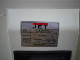
I've got a Jet JWP-12 thicknesser


which up until now has always been 'somewhere' in the workshop. When I wanted to use it I have lugged it about (30kg of it) onto whatever surface I have available. getting fed up with this, I made a trolley for it this morning:


I'm not sure what will live underneath it, some thing that don't care if they are covered with sawdust.

It's a nice thicknesser and I have used it quite a bit, probably more than I thought I would. It's a luxury being able to use almost any wood and get it reduced down to size in flat cuboids.

One thing that irritates the rats out of me is the way the infeed and outfeed 'tables' fall down. They are designed to fold up for storage but there's no positive latch action to keep them up and so they are continually falling down. Once down they always seem to be at shin height.


So, I have 3D printed a lever arrangement that is designed to hold the tables up in a positive way.


The lever is attached to a base that screws onto the trolley and allows the lever to swing up under a nice flat area under the edge of the table. When in the down position the base just clears the side.


There's a video of the latches here:


And the Thingiverse files are here:

https://www.thingiverse.com/thing:3512480

Lamy Pico Fix

My Lamy Pico pen


that goes everywhere with me broke recently. It had been sticking when telescoping it, but I hadn't realised why. I thoughty there'd been a build up of fluff or something, but it turned out that the end had broken. You can see on the right hand side of the pen that it's at an angle. the thread has broken on the part that is unscrewed when replacing the refill. This is a shame. I could get it repaired, but even then it's likely that the same thing would happen. So I decided to have a go at making a new part.

I dismantled the broken part. There's a spring and a sliding part that holds the refill. The pen telescopes, so there's quite a bit of movement of the refill.


I realised that I could re-use these parts, although I have ordered some bits and bobs if I want to have a go at completely replacing them.

This is the sort of job that I got a lathe for, so I found some brass rod, and machined a replacement part from solid brass.


I took dimensions from the original, which gave me a starting point. The thread was 11.4mm x 0.8mm pitch, if anyone wants to do this themselves. That thread fits nicely in the barrel of the pen. I manually adjusted the part to make it work with the telescoping mechanism. This was a bit tricky as it didn't work too well at the start, but by removing small amounts of material I got it working as well as the original.

I used abrasive paper and a burnish to finish the outside, and it fits well on the pen:


I added the radius on the end using a file on the lathe. I have no radius turning tool for my lathe.

The pen when in the extended position:


The extra material is noticeable, but not unpleasant, and the brass is nice and shiny. I may remove the paint on the pen to match the new part, or I may not. I'm undecided at the moment. It may be a good idea as it is wearing off anyway in places, so would be neater if removed.


I've done a video of this, if you want to see it moving:


Friday, 22 March 2019

Reuse

This is an old dressing gown


that has been in the 'could be re-used' pile for many years.
It seems to be big enough to cut up


sew hems into


and add a draw string (rope).


With the ends of the rope attached to a leather fixing...


... it's a bag!


It's a big bag for carrying other bags and shoes and stuff when my arms are full of a small person going to nursery...


Wednesday, 20 March 2019

Evolution of Another Thing

Time to try to fix something. Or replace a lost thing, really.
Here's the items involved:


If you resign both wizards then you see that there's a nether region problem with one of them:


The plug for the pepper is missing. OK, this looks simple. Hmm, no it's not. The plug that still exists (ok, exists and is locatable), is a bit flexible. So, the replacement will also probably have to be as well. Hmm, never printed in flexible filament, is it even possible on my printer? A bit of internet searching and it sounds like it might be possible even with my bowden tube Fisher printer. The extruder design (at least the new one on the printer I fixed recently) has the required lack of gaps along the filament path. OK, order some flexible filament. How much? OK, order a sample. It's something I've wanted to have a go at for a while, just never got round to it.

Hmm, this is going to be near food, is PLA food safe? Looks like yes it is.  Unfortunately 3D FDM printed PLA doesn't seem to be due to the small gaps between layers trapping food which then decays. Hmm, is that a problem in an application where the 'food' sits on a pot for years and years anyway? OK, it might be, lets look at getting some HDPE in rod form and machining a plug on the lathe. That will be an interesting exercise as well.

Measurements  of the plug done and I have a model in OpenSCAD.


It looks printable too, if it is printed the right way round. There's a small overhang but it should be fine.

There, it is fine:

First attempt. fail. The 'elephant foot' effect of the first layer has caused the end that is first inserted to be too big for the entrance and the part won't fit at all.
OK, print another one with a smaller diameter at the end.

Done:


Does it fit? No. Still too big, but it's close and what are knives for anyway? A bit of a trim and it's in:


Unfortunately, the reason for the flex in the plug becomes apparent as this rigid plug pushes in most of the way then stops (it's got a taper), but then has no 'hold' and easily comes out again. So flex is important.

What about in the salt pot? What? It doesn't fit at all. Turns out that the holes in the ends of these two pots are different sizes. Not a surprise I suppose, as they are pottery. i wonder if the plug has been lost because the hole is bigger in the pepper? Maybe, or when they made these pots an fitted plugs they had a selection of slightly different sized plugs? I don't know, but it does mean that measuring the salt plug to make a new pepper plug wasn't ever going to be a properly grounded tactic.

The sample flexible filament has arrived. Time to have a go at a flexible version.
I find it prints with the settings I had for PLA. No changes at all. The parts


The two on the left are the flexible prints. I added a rounded end to make it easier to fit in the pepper pot. I did two as there was some discolouring on the first. The slicing tried to do retraction which didn't work as the filament was curved in the bowden tube so there's a bit of build-up at one point round the part, but they are pretty good, even so. And they fit:


They fit nicely, in fact.

The HDPE has arrived as well, so I turn a part on the lathe. It's here in the line-up:


It has come out a bit larger than the 3D printed parts as I needed to be able to hold the part in the chuck. It's not as flexible as the printed parts either, but it does fit.


I think the best fit so far is the flexible print. Opinions vary, however.

Saturday, 16 March 2019

Plantation Shutters

Plantation shutters (I'll use shutters from here on) are fairly popular here

in the UK. They are expensive, though, so when we were looking to put them on our windows (a few years ago now), the price was around £1000-£2000 per square metre. With thirteen windows, each about 2 sq m, the bill was getting quite large. So, I had a look at making them. This turned out to be a long process, and the shutters weren't fully complete until a couple of years later. This post is an attempt to document the process i went through to make these shutters. Is it worth the effort? Well, I was happy with the result (people have commented on them) and I worked out that the cost in parts was around the £25 per sq m mark. That's a lot cheaper than bought in ones (although I think the price may have dropped a bit over time from when I first looked). Of course, it takes time and effort, but that was mostly fun. It got a bit wearing around window 6, but things like a patio door double decker version made things a bit more interesting. Of course the 8 panels I had to do for that (the equivalent of 4 windows) tempered the excitement a bit.

What do they look like? Well, like this:


That's a standard sized window, we have several like that. The shutters are in four panels, pairs of panels bi-fold on hinges so you can open them and get full light from the window.


You can open and close the slats with a central control rod;


The slats must be closed when folding the panels back to the fully open state.
The patio doors have a double decker arrangement, so you can open the top or bottom independently.


 The panels latch into place with magnets set into the panel edges:
 

There are quite a few of these per panel.
Some of the windows required a frame that was surface mounted


 and some required other arrangements:


The control rods are attached to the slats using staples which I hammered in by hand. After a couple of hundred staples I got the hang of it.


The slats are elliptical on profile, I used a router bit to shape them on a router table from rectangular stock. All of the shutters and frames are in pine. It is finished in Osmo wood wax which is a stain, rather than paint. This means it doesn't affect dimensions after it is applied. It also allows the grain of the wood to be visible.

The windows didn't have window sills so I added some where needed:


Of course, there was a window that required three panels rather than four:


And the one odd sized window:


That is a single panel, which is hinged so you can open it if needed. It's also the last window I fitted shutters to.

These are the pins and router bits that I used:

https://gb-woodline.glopalstore.com/products/plantation-shutter-set


Thursday, 14 March 2019

Quick Thing (And filament comparison)

I don't know what I did before I got my 3d printers. How did we get little things like separators for clothes hangers? A couple of days after the request and I'd designed the thing and printed several:


(Some are pink as I had the filament and decided I'd not be using it for much, so may as well use it here).


The time to get these hooked markers included ordering and receiving a reel of white filament.


That's the set so far, and the owl-eyed among you might spot a difference in the white ones. I had a small amount of white filament left over from a faberdashery order and ran that through the printer, closely followed by the pink (on the fisher I have found I can push a new batch of filament into the extruder after some that has run out and all is fine, no need to splice it). I also order a reel of cheaper white filament from ebay to see what it was like (for one quarter the cost). It prints and is fine for prototypes, and maybe some parts as well, but it looks like there's nowhere near as much pigment in the filament. Hence the less that brilliant white of some of the markers in the picture. The faberdashery filament is definitely more saturated in colour. But it's a lot more expensive...